Progress Report
Quantum Cyberspace with Networked Quantum Computer[4] Superconducting networking technology
Progress until FY2024
1. Outline of the project
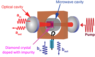
This research and development project aims to realize a “quantum transducer,” a key technology for scaling and networking superconducting quantum computers. The transducer converts microwave photons—used to carry quantum information in superconducting qubits—into optical photons within an ultra-low-temperature environment. We focus on using electron spin ensembles associated with nitrogen-vacancy (NV) centers in diamond as the medium for this wavelength conversion.
To achieve this, we have tackled several technical challenges: implementing optical cavities containing bulk diamond crystals, maintaining cavity stability at millikelvin temperatures, and integrating them with microwave resonators. We have designed and employed a custom low-vibration, cryogen-free dilution refrigerator to overcome these difficulties.
2. Outcome so far
- We successfully stabilized an optical cavity in a cryogen-free dilution refrigerator at millikelvin temperatures.
- We achieved stable operation of an optical cavity even with a bulk diamond crystal placed inside.
- We designed, fabricated, and evaluated a hybrid microwave–optical resonator device under cryogenic conditions.
- We developed a theoretical model for the microwave–optical photon conversion and performed numerical simulations of the conversion efficiency.
- We realized the initial demonstration of coherent-state microwave-to-optical conversion.
Regarding 1, we could stabilize an optical cavity in a cryogen-free dilution refrigerator, where the pulse tube's cold-head induces vibrations, making optical cavity stabilization very challenging. Regarding 2, we managed to stabilize an optical cavity, even including a bulk diamond crystal. This manifests that the quantum transducer developed in this project is technically possible. Regarding 3, it is the transducer device. A diamond crystal must be placed in microwave and optical cavity modes. To this end, we designed and tested a combo-cavity (Figure 2). Regarding 4, we developed a theory of the microwave-optical photon conversion and simulated the conversion efficiency. Regarding 5, this marks a major milestone in our project. We are currently preparing experiments to convert truly non-classical photon states—such as those generated by superconducting qubits—into optical states.

3. Future plans
Using the developed transducer device, we first convert classical weak microwave or optical signals to demonstrate the proof-of-concept of the quantum transduction. We will then convert non-classical quantum microwave photons prepared by a superconducting qubit to optical photons. We will collaborate with the "Development of Integration Technologies for Superconducting Quantum Circuits" team for these objectives.